Team 9 – 3D-Printing Assembly and Inspection Fixtures
Topic:
3D-Printing fixtures for part assembly and inspection while considering the durability and economic advantages
Problem Statement:
With the support of the University of Maine, the Advanced Structures and Composites Center, and Tri-Mack Plastics our team researched and will be producing 3D printed fixtures for a variety of manufacturing processes. The fixtures to be completed include one assembly fixture, 3 CMM inspection fixtures, and one laser engraving fixture. The project will be focused on the economic advantages and technical capabilities of fixtures created with several 3D printing techniques. Three deliverables for our project include delivering working fixtures to the sponsor, creating a design guide the sponsor can use to create printed fixtures in the future, and an economic analysis of the benefits of printing fixtures.
Photos:
To view our photo album for our 3D prints, click here
Design & Printing:
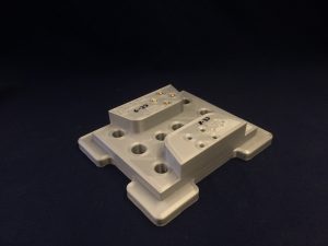
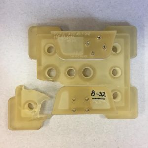
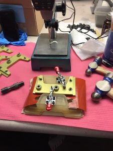
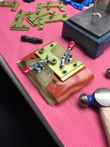
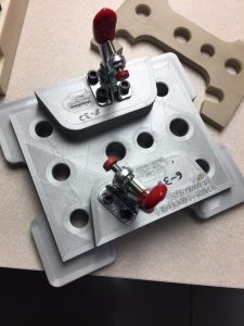
Assembly Fixture
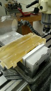
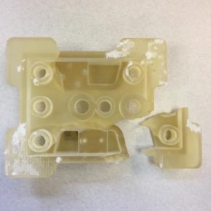
This fixture was redesigned to reduce material used while retaining functionality and strength. Each fixture was printed using a different printer; yellow was printed on the ProJet 5000, white was printed on the Fortus 900mc, and gray was printed on an Ultimaker 2+. This fixture requires clamps to hold the part in place while being assembled. Tapping plastic and printing threads are both complicated, messy, and don’t result in decent threads. The photopolymer print used expanding press fit inserts since heated ones would weaken the set resin, the press fit inserts can be seen in the 4th picture. So the two thermoplastic prints, white and gray, received inserts heated by a soldering iron and pressed into the plastic. The heated inserts can be seen in the last picture. The heated inserts smoothly pressed into the print and did not appear to have any issues. All printed fixtures held the part firmly. The text on the ProJet 5000 print came out the best and while the text on the Ultimaker 2+ print is difficult to read as seen in the last picture. The Fortus 900mc print text had to be rewritten in marker because of the poor quality. The FDM prints came out flat on the bottom with almost no warping, however, the PolyJet print warped in the oven when it was having the support material removed.


For more photos, click here
_________________________________________
CMM Fixture One
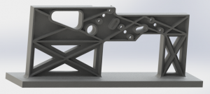
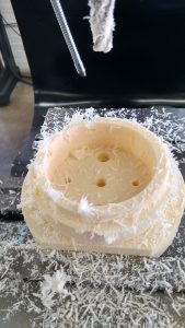
Due to the long unsupported vertical section in the initial design of CMM inspection fixture one as showing in the first picture below, it was necessary to redesign the fixture for 3D printing. The main considerations in the redesign included re-orienting the vertical section horizontally, adding extra supports to the fixture, ribbing the back side of the mating surface, changing threading techniques, and removing material where not necessary to reduce the cost to print. The supports added to the fixture had to be carefully placed so as to not interfere with the CMM probe as it inspects the part features. The redesign was also done with the intent that the hardware and steel plates already utilized by many of the CMM fixtures at Tri-Mack could be reused. Changing threading methods meant the threaded holes in the original design had to be enlarged in order to press in threaded inserts. The second and the third pictures show the design changes made to the fixture in a CAD rendering. The last picture is showing the printed fixture from PolyJet printer and made of VisiJet M5 MX.


For more photos, click here
_________________________________________
CMM Fixture Two
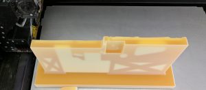
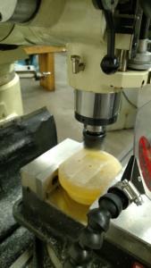
This is CMM fixture two and it was redesigned to test post processing methods of 3D printed parts. This part requires a tolerance of 0.0005″ around the top most diameter, unprintable on the printers we have available to us. So the diameter was expanded by 0.050″ in the print to be removed later by a CNC mill. The print from the ProJet 5000 was printed with VisiJet M5 MX part material and S300 support material. When printing the initial layers of support material the printer missed several layers in the middle of the part resulting in part material filling the void. This produced ridges on the bottom of the finished part which had to be milled flat in post processing.


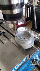
For more photos, click here
_________________________________________
CMM Fixture Three
This fixture was redesigned to speed up the inspection process on the CMM. This part requires 100% inspection so the more parts that can be measured at once the less time the operator wastes loading and unloading single parts. The dovetails were added on the top and right side so that multiple fixtures may be printed and fit together in a grid pattern on the CMM table. With the new design, Tri-Mack will be able to connect as many fixtures as they want together in vertical, horizontal, or diagonal orientation. This fixture has been printed on the Projet 5000 and will be printed on the Fortus 900mc by 03/31/17. The material used to print the CMM inspection fixture 3 on the ProJet was VisiJet M5 MX. After the fixture was printed, it was placed in the oven for two hours. The oven heats the support material (VisiJet S300) to a molten state causing it to drip away and reveal the surface of the fixture.


For more photos, click here
The team conducted a simple test in order to help determine the ideal clearance for dovetails printed on the ProJet. The test block was printed as separate parts in order to eliminate the possibility of fusing. The idea of the dovetails is to print fixtures individually and connect them after the print so a fusion in the test results would not be of any benefit to the redesign. The tolerance test part can be seen below in Figure X. Though all the dovetail blocks fit in each of the slots, the team decided to redesign the fixture to include a .0075” clearance. This clearance was chosen in order to allow for variation in the overall dimensions of the fixtures and ensure there would be sufficient clearance for them to fit together even if different printing methods were used.

Weekly Update:
04/26/17
The team is working on the presentation which will be held on the 3rd of May ( Maine Day), and the final report which due May 8th. We are done with printing fixtures that we are supposed to print in our project. The team has decided not to send all the printed fixtures to Tri-Mack before the presentation for tasting. Tom and Jeff are ready to go to ASEE ( American Society of Engineering Educators ) conference in Boston on the next Saturday 04/29. They are going to present our final findings and talk about the project.
04/21/17
The team is getting close to the end of our capstone project. The presentation and the speech are about to be ready to present in the ASEE ( American Society of Engineering Educators ) conference. At the same time, printing the rest of the fixtures is still in the process. Data needs to be collected for the final report. We have measured all the fixtures that we printed so far. The table below shows the measurement of 3 different types of the printed CMM fixture 2.
| CMM fixture 2 | |||
| FDM (in) | ProJet (in) | Ultimaker (in) | |
| Outer D | 3.558 | 3.531 | 3.561 |
| Inner D | 2.951 | 2.919 | 2.938 |
| Cab | 2.942 | 2.916 | 2.937 |
| Height | 2.015 | 1.986 | 2.005 |
04/14/17
The team is in a good shape and everything is going as scheduled. As this week the team is collecting all the data and all the numbers so that we can include as many as we collect in the final report. Printing the fixtures is currently in the process. We have done printing CMM fixture one this week by the ProJet printer and it came out very good (it can be seen in Design & printing section ).
04/07/17
The team is still printing the rest of the fixtures, and will start working on the final report IR 4 since we just received IR 3 back after correction. The team is putting all their effort to finish everything two weeks before the due date. A great news is two members of our team will have the chance and present at the ASEE ( American Society of Engineering Educators ) conference about our findings. This is a good opportunity for our team to introduce our ideas and enhance the engineering field.
03/31/17
The team will continue printing the other fixtures. Earlier this week, Tri-Mack contacted us and has sent us the results from testing the Assembly fixtures that we sent them at the beginning of the semester. They started the test with the PolyJet fixture. They found that the fixture is light and it was bouncing and moving around the table when the threads were being staked. When the threads are staked in, the protruding metal pieces circled below fall in that hole. They found also that the plastic is soft and does not scratch the anodized aluminum as the metal fixture sometimes does. Tri-Mack also attached photos of the fixture as it was broken on the 8th part.
They also have tested the Ultimaker 2 and the Fortus fixtures and they have found that the fixtures look as good as new after the testing process was done. Even though 17 parts have been assembled to the Ultimaker 2 fixture, and 8 parts have been assembled to the Fortus fixture. Moreover, they think that the hand tapped threads are a bit more difficult to work with than the inserts. Also, one of the four bolts would not go down all the way.
03/24/17
The team is back from spring break and will continue printing the rest of the fixtures. Tri-Mack contacted us and they will test the assembly fixture this week and they will send us the feedback as soon as they get done with testing.
03/06/17 – 03/17/17
Spring Break
03/03/17
The team is ready for the break and have done with Interim Report 3 which was due on Wednesday 1st, 03, 2017. The team was successfully printed 2 fixtures, CMM fixture three was printed in 2 different 3D printers, ProJet 5000 and Fortus 900mc. The other fixture that the team was able to print is CMM fixture two. The printer used is ProJet 5000.
02/26/17
The team is all set with designing the fixtures, and ready to print them before the spring break and send them to Tri-Mack over the break for testing. IR 3 is due 1st of March, and the group is working well on it.
In the picture below, we were trying to figure out what is a good clearness for one of the fixtures (CMM 3), so we printed a tolerance test. It was printed from ProJet (5000) and the material is VisiJet M5 MX. In order to get the exact tolerance of the dovetails and the other piece, and to avoid any kind of breaking, we printed them separately. We think that if we printed them as one piece, it would be difficult for us to know what is the best clearness.
02/19/17
We have printed a red and a white rose with different 3D printers. Ultimaker FDM printer was used for the red rose and it was made of thermoplastic with supported material. The white rose was made of m5 MX and wax with supported material and it was printed by ProJet (5000). We used different materials in printing the roses to see the actual result. We have found that the wax is better as you can see in the picture, because it is easier to melt and take the actual shape than the plastic.

02/12/17
Designing the fixtures and make them ready for printing and working on Interim Report 3 are now is our concern. We still don’t get feedbacks form Tri-Mack, they will send them as soon as they could. So, we can include them in our Interim Report 3, which is due on the 3rd of March.
02/05/17
The team is waiting for Tri-Mack’s feedback, so that the team will know which printer will be used to print all the five fixtures. Meanwhile, the team is working on designing the fixtures and make them ready for printing.
01/24/17
Revised Interim Report 2 is due the 25th of January, and the team is doing all their best to revise it. Tri-Mack has all the 3D print assembly fixtures that we printed them for testing. They will test them and give us their feedback soon.
12/12/16
Winter break is almost there and our 3D print assembly fixtures are about to be done and to be sent to Tri-Mack for testing.
12/04/16
The team is setting together and working on the Interim Report 2. Our team will be able to 3D print three assembly fixtures and send them to Tri-Mack for testing over Winter break. The fixtures will be printed by three process, Fortus FDM, PolyJet and desktop FDM.
11/25/16
The visit to Tri-Mack took place on Tuesday the 22nd of November 2016 with Jonathan Roy from ASCC. The team is ready for the Thanksgiving Break, then come back and work on the final report.
11/17/16
The team is ready and all set to visit Tri-Mack in Boston on 11/22/16. The team is well prepared and have all the questions that needed to be answered. Moreover, the team sat together and worked to finish the Interim Report Revision.
10/28/16
Done with the Interim Report 1 for the project and we will get it back within a week or so. The team received the parts from Tri-Mack through Jonathan Roy. Try-Mack sent 3 parts and they will send the rest in the next week.
10/20/16
Our team had the 2nd meeting with Tri-Mack on Monday 10/17/16, the team had the chance to ask more questions about the project and ask for the specifications. The team has not received the assembly parts yet. Try-Mack will do the best to send them by the end of this week.
10/12/16
Our first kick-off meeting with Tri-Mack. Introduced the project and had the chance to asked a few questions. Our team will receive assembly parts designed from Tri-Mack to have an idea about the Fixture. We will have our next meeting with Tri-Mack on Monday 10/17/16.
Team:


Team Leader: Im from a small town in the hills of Vermont, called Brookfield, where I’ve lived my whole life with my older brother and younger sister. In my free time I like playing soccer with my coed team, and hiking in Acadia. I am currently an intern with Old Town Canoe where I am learning how to design and build systems that make employees safer and reduce production time. I also work in the machine tool lab on campus as a tool crib attendant and lab TA. After school I plan to get a job with a renewable energy company back in Vermont.

I’m an international senior Mechanical Engineering Technology student from Saudi Arabia, Jeddah. I’m a former operator for Saudi ARAMCO Oil Company for 4 years. In 2011 I started studying at the Intensive English Institute (IEI) at University of Maine. Then, in 2013 I started my Bachelor degree in Mechanical Engineering Technology (MET). I had a summer training job in Saudi Arabian Airlines in 2016. There, I learned about airplanes and their maintenance it was a very helpful training. I like playing soccer with friends whenever I have the chance to. After I graduate, I’m planning to go back to Saudi Arabia and start my career as an engineer.

I am a Senior Mechanical Engineering Technology graduating in May of 2017. I have worked at Lanco Integrated in Westbrook, Maine and Elmet Technologies in Lewiston, Maine. Upon graduation I’m looking to pursue a career in manufacturing processing. My Hobbies the include mountain biking, snowboarding, and being outdoors.

Born and raised in Massachusetts, started my time at the University of Maine in Fall of 2013. I am a fourth year student currently working on my capstone project and finishing up my B.S. in Mechanical Engineering Technology. In my spare time I like to work on and ride motorcycles. I also enjoy flying small airplanes and am currently working on attaining my private pilot’s license. I was interested in the thermoplastic mold project because I would like to expand my knowledge of the capabilities of 3-D printing and also the material properties of the various plastics we will be using to achieve our goal.
Contact Info
Tom Zani: tommy.zani@maine.edu
Ammar Ayyash: ammar.ayyash@maine.edu
Ryan Pitas: ryan.pitas@maine.edu
Jeffrey Graveson: jeffrey.graveson@maine.edu
Project Sponsors
- The University of Maine, School of Engineering Technology.
- The University of Maine, Advanced Structures and Composites Center (ASCC).
- Tri-Mack Plastics and Manufacturing Corporation.