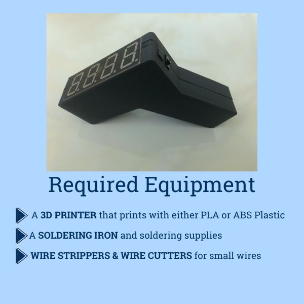
How to make a 3D-printed infrared thermometer
 Many reopening plans require (or will require) real-time non-contact temperature readings of people entering buildings and other public spaces. Unfortunately, the demand for reliable infrared (IR) thermometers is still very high and the commercial supply is limited. By following this guide, developed by researchers at UMaine’s VEMI Lab, you and other hobbyists can help bolster the supply of IR thermometers, allowing your local businesses, nonprofits, and other entities to comply with public health guidance and reopen their doors.
DISCLAIMER: DO NOT USE THIS FOR MEDICAL PURPOSES. It is designed to read an *approximate* temperature, to see if someone likely has a fever; it is NOT to be used for a medical diagnosis of illness.
PARTS LIST
Prices for parts may change. At the time of publication, it was possible to acquire all the needed parts from the sources below for approximately $60.
| Arduino Pro Mini 328 | https://www.sparkfun.com/products/11113 |
| 1K Ohm Resistors 20ct | https://www.sparkfun.com/products/14492 |
| 10K Ohm Resistors 20ct | https://www.sparkfun.com/products/14491 |
| Breakaway Pin Headers | https://www.sparkfun.com/products/116 |
| Battery Clip | https://www.sparkfun.com/products/91 |
| Temperature Sensor | https://www.sparkfun.com/products/9570 |
| Display | https://www.sparkfun.com/products/11409 |
| On/Off Switch | https://www.sparkfun.com/products/102 |
| Pushbutton | https://www.sparkfun.com/products/11995 |
| Protoboard | https://www.sparkfun.com/products/8808 |
| F/F Wires 20ct | https://www.sparkfun.com/products/12796 |
| 9V Battery | Local Store |
| FTDI Board** | https://www.sparkfun.com/products/9716 |
**FTDI board is optional and a maximum of 1 is needed. See Step 4 of Instructions
Why these parts?
The Arduino Pro Mini is the smallest reliable microcontroller we could buy, which makes it ideal for embedding in a 3D-printed case. The pin headers, protoboard, and F/F wires are not required for functionality, but will make the finished product much more robust. The 3D-printable case was designed with the switch, pushbutton, and display listed above; changing any of these will require a change in the case file.
This temperature sensor is NOT medical-grade. The sensor included in this guide has ±0.5℃ accuracy, while a medical sensor would have ±0.1℃ accuracy. As noted above, DO NOT USE THIS FOR MEDICAL PURPOSES. It is designed to read an *approximate* temperature, to see if someone likely has a fever; it is NOT to be used for a medical diagnosis of illness.
A higher-precision version of the temperature sensor (which is still not medical-grade) is available for purchase through Digi-Key Electronics.
INSTRUCTIONS
Step 1: 3D Print Case
Download the 3D-printable case here: https://bit.ly/2TxaxFv
This case is designed to be printed in two pieces that clip together.
The print is designed for the following settings:
- 0.2mm slice width
- 10% infill
- Automatic Support Generation: ON.
- Shells: 3
Begin printing the first half of the case before you start assembling your components (below). The print will likely take longer than your assembly process, but check on it periodically to make sure it hasn’t failed. When the first half is done, remove it from the printer and begin printing the second half.
Step 2: Download the Code
Download the IR Thermometer code here: https://bit.ly/3cE2bUe
In order to install this program, you will need to download the Arduino software from www.arduino.cc
- Open IRThermometer.ino with the Arduino software.
- Open the Library Manager by selecting the “Sketch” toolbar > “Include Library” > “Manage Libraries”.
- In the Library Manager, search for and install:
- SevSeg
- Adafruit_MLX90614
- Close the Library Manager.
Step 3: Assemble Electronic Components
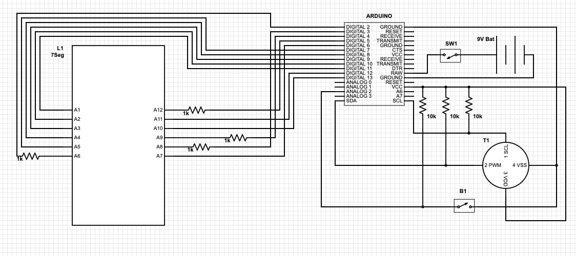
- SCHEMATICS: Download the following datasheets and have them handy while you’re working on this project. You will need them to wire the circuit correctly.
Temperature Sensor: https://bit.ly/2zltlkh
7-Segment Display: https://bit.ly/3hgOHAv - WIRES: The wires purchased for this project will need to be edited slightly for use. Where a pin header is used, socket the wire on normally. Where thinner wires and leads must be connected (in the case of the Display and the Thermostat), do the following.
a. Remove the black plastic casing around one of the F adapters by lifting up the plastic tab directly above the visible metal. With the plastic removed, insert the pin into the metal female adapter, and apply solder to the joint. This will function the same as soldering a wire to a component, but the joint will be significantly stronger. - THE PROTOBOARD:
a. This board is not an array of isolated contacts. Instead, many of the contacts are connected. If you look very closely, you should see lines of green connecting a few of the dots at a time. Most of these are 3-dot lines, but some will be 4 or 2. Use these connects to connect wires to resistors and to each other.
- You will need: The Arduino Pro Mini and the Pin Headers. (Figure 3).
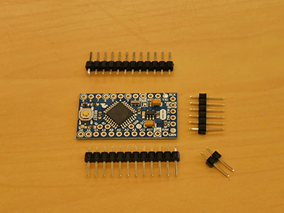
Figure 3 a. Break off 2 12-pin, 1 6-pin, and 1 2-pin headers. Solder the pin headers to the Arduino board. (Figure 4)
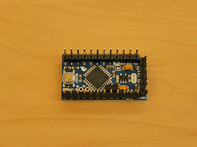
Figure 4 - You will need 12 wires, the LED display, 4 1k Ohm resistors, and the protoboard (Figure 5)
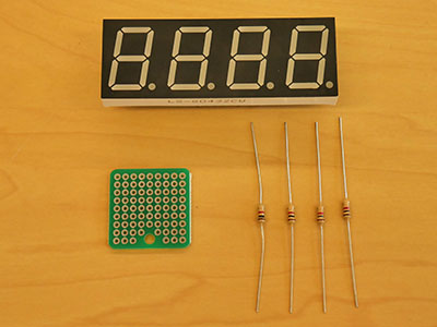
Figure 5 a. For each of the wires, remove the plastic jacket from one of the ends. This can be accomplished by using a pointed object to raise the plastic tab on the side and pull the jacket off. When you’re finished, the ends of the wire should look like Figure 6.
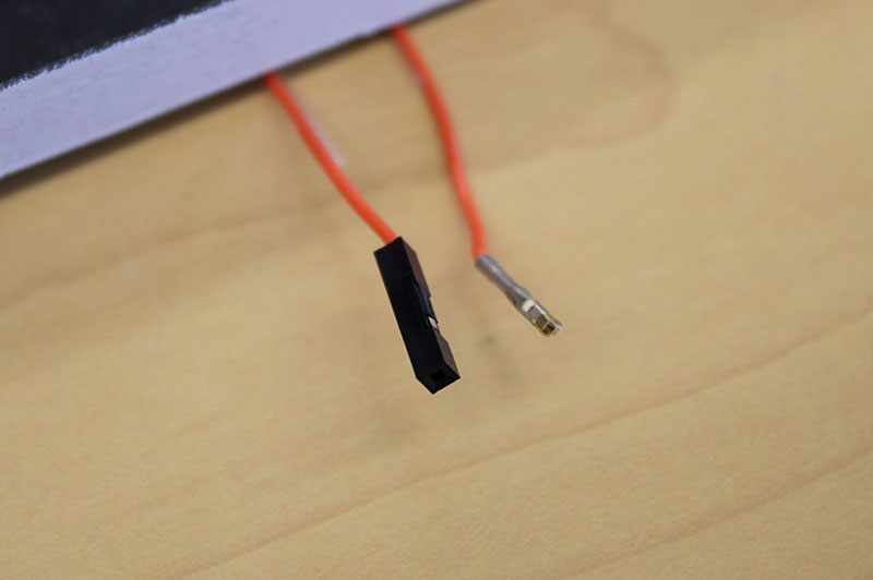
Figure 6 b. For each of the 12 pins on the display, solder the non-jacketed end of the wire to the pin. (Figure 7).
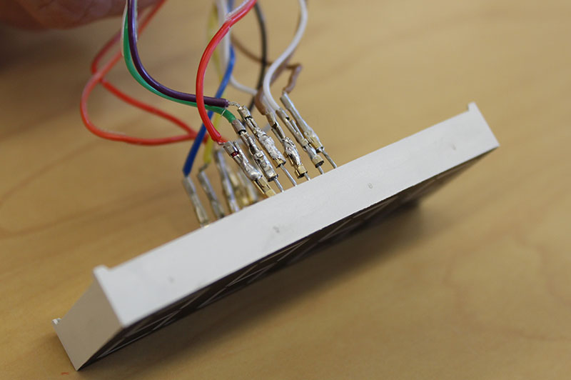
Figure 7 c. For pins 1-5, 7, 10 and 11, connect the jacketed end of the wire directly to the appropriate Arduino pin.
d. For pins 6, 8, 9, and 12, cut the wire in half. You will solder each of these halves to the protoboard, and solder a 1k Ohm resistor between them, then follow the schematic (Figure 2) and socket the other half to the appropriate Arduino pin. (Figure 8)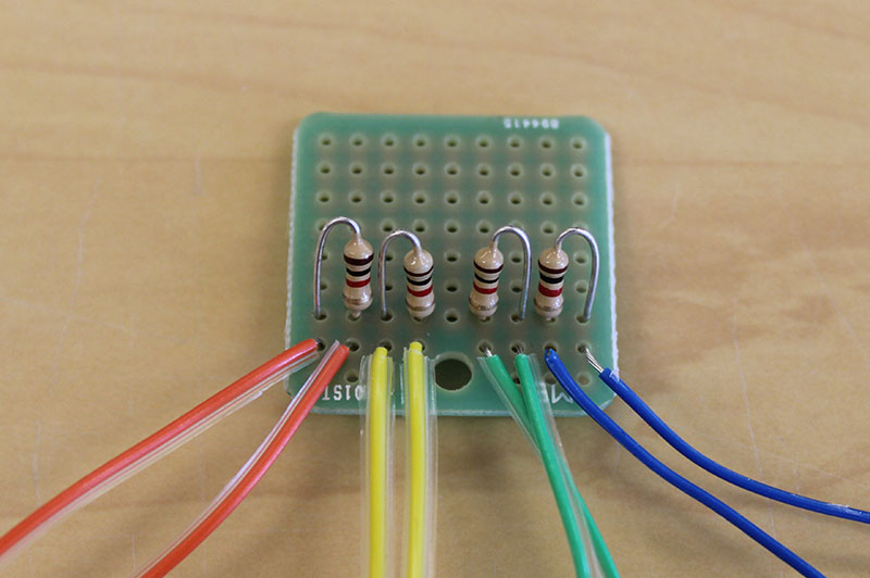
Figure 8 - You will need: 4 10k Ohm resistors, 1 Temperature Sensor, 1 pushbutton, 1 protoboard from step 2. (Figure 9).
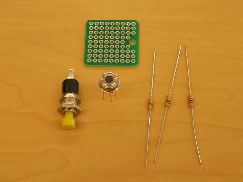
Figure 9 a. The rest of the protoboard can be used to solder the most advanced part of the circuit. Each of the 3 10K Ohm resistors should be soldered to the board and connected at one end via the built-in channels or solder bridges. These will be the pull-up resistors for the Thermostat circuit. (Figure 10)
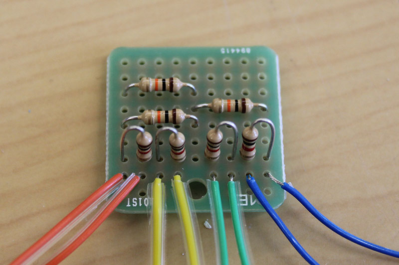
Figure 10 b. Solder a wire to each leg of the temperature sensor (Figure 11), then cut those wires in half. Solder BOTH of the freshly-cut ends of each wire to the Protoboard as shown (Figure 12 & Figure 13), and the other open end will connect to the Arduino as shown in the schematic (Figure 2).
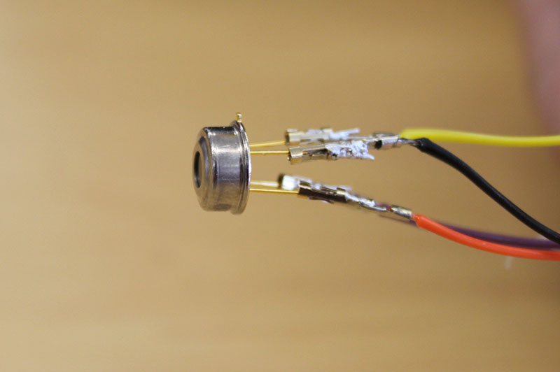
Figure 11 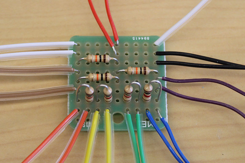
Figure 12 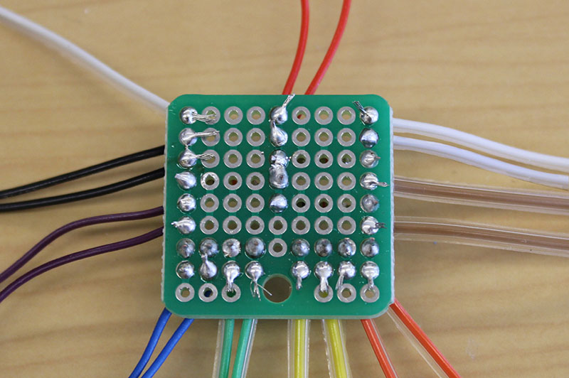
Figure 13 i. Two sets of wires will be soldered to the free end of two of the resistors and the jacketed ends of the wires will connect to the SDA and SCL pins on the Arduino
ii. One set of wires will be soldered to the common end of the resistors and the jacketed end of the wire will socket onto the VCC pin.
iii. One set of wires will be soldered to a pair of connected open on the protoboard and the jacketed end of the wire will socket onto the GND pin.
c. IMPORTANT: When looking at the Thermostat datasheet, remember that the pin out is drawn as if looking DOWN from above the sensor. (Figure 14)
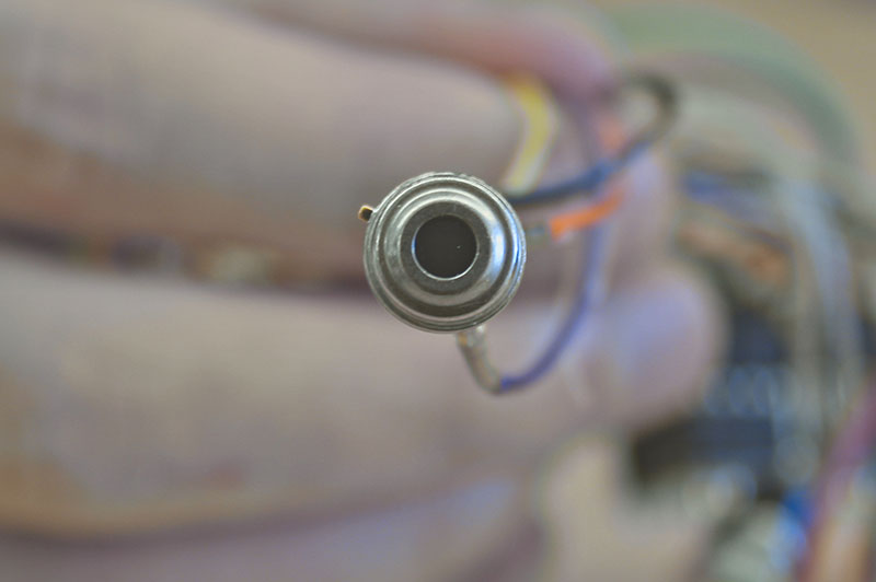
Figure 14 - To connect the pushbutton, you will have to cut a wire in half, and clip both Female ends off as well. Solder one wire between the 3rd 10K Ohm resistor and one side of the button, and solder the other wire between the other side of the button and ground section of your protoboard. Then solder another wire to a contact connected to the 3rd 10k Ohm resistor and connect it to the Arduino on pin A2.
- You will need: 1 battery clip, and 1 switch
a. Cut the red wire on the battery clip, and solder both halves of the red wire to 2 different pins on the power switch (middle pin and one of the outer pins) (Figure 15). Then plug in the battery clip’s adaptor to the 2 pins labeled RAW and GND (RAW should be the RED wire)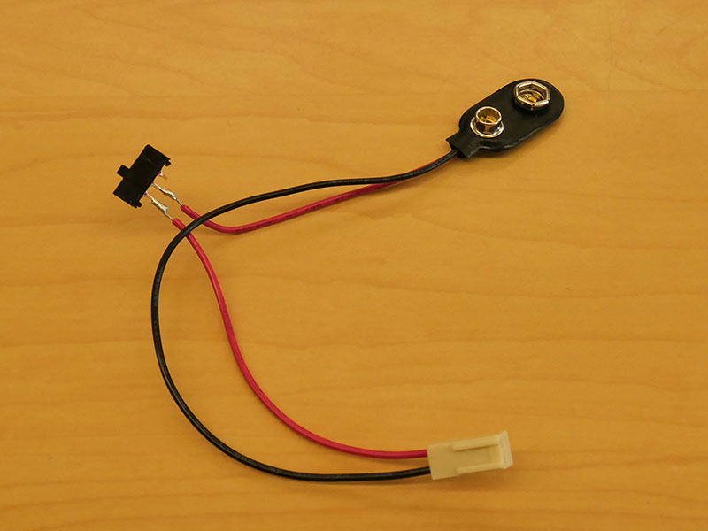
Figure 15 - The final circuit should fit into the case like Figure 16. Figure 17 has been included to show what the component placement looks like without wires cluttering the view.
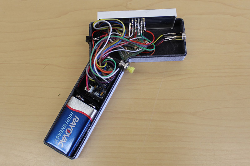
Figure 16 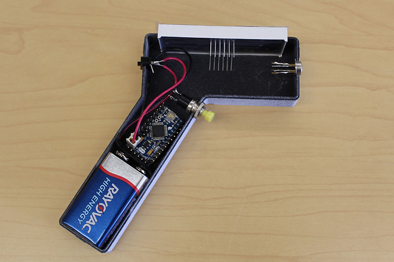
Figure 17
Step 4: Program the Board
To begin programming the Arduino, you have two options. Either (a) use the FTDI board, or (b) use an Arduino Uno to program your board.
Before you upload the code, check over the Thermometer program, making sure all of your I/O Pins are the same ones coded into the program.
To upload it either:
-
- Slide the FTDI board onto the correct pins of your Arduino; your Arduino software should recognize the board.
- To use the Arduino UNO to program the Pro Mini:
-
-
- CAREFULLY remove the ATmega328 chip from the UNO.
- Connect the UNO’s 5V pin to the Pro Mini’s VCC pin.
- Connect the UNO’s GND pin to the Pro Mini’s GND pin.
- Connect the UNO’s TX pin to the Pro Mini’s TX0 pin.
- Connect the UNO’s RX pin to the Pro Mini’s RX1 pin.
- Connect the UNO’s Reset pin to the Pro Mini’s RST pin.
- Open the Arduino software and select Tools>Board>Arduino Pro or Pro Mini.
- Upload your program!
-
-
- TEST THE THERMOMETER. Hold the sensor 1-2 inches from your forehead and press the pushbutton. When you release it, your temperature should be shown on the Display. Do this multiple times. Do it on another person if you can.
- CALIBRATE THE THERMOMETER. You may have noticed that the thermometer is consistently ready a little low or a little high. It requires calibration. Open the arduino code and look for the variable tempOffset (It is one of the first lines of code and surrounded by ******). It is set to 7 by default, because that was the most common offset we needed for our sensors in-house. Increase or Decrease this value to shift your thermometer so the average healthy temperature measured is 98.6 F. Re-uploaded the program to the arduino, and you’re done!
Only one FTDI board or Uno will be required for this project no matter how many thermometers you make. Once the program is installed the board will not be needed again.
BE SURE TO PROGRAM THE ARDUINO BEFORE YOU COMPLETE THE FINAL ASSEMBLY. With all of the components installed, there will be a very snug fit and re-opening the device may prove difficult.
Step 5: Final Assembly:
When both halves of the print are done, make sure they fit together and install the components. You may need to file some of the openings for the components to fit properly. For the completed product, all of the components should fit snugly into their respective openings.
Step 6: Testing
When you turn the device on (by flipping the power switch), you should see the number “0”. When the button is pressed and held, random (irrelevant) segments will temporarily be lit, and when you release the button, the display will show the person’s temperature. It is recommended that this process is repeated a few times to get a more accurate estimate.
Infrared thermometer designed by the VEMI Lab. For any questions, contact VEMI Lab.