Operating the CNC Foam Cutter
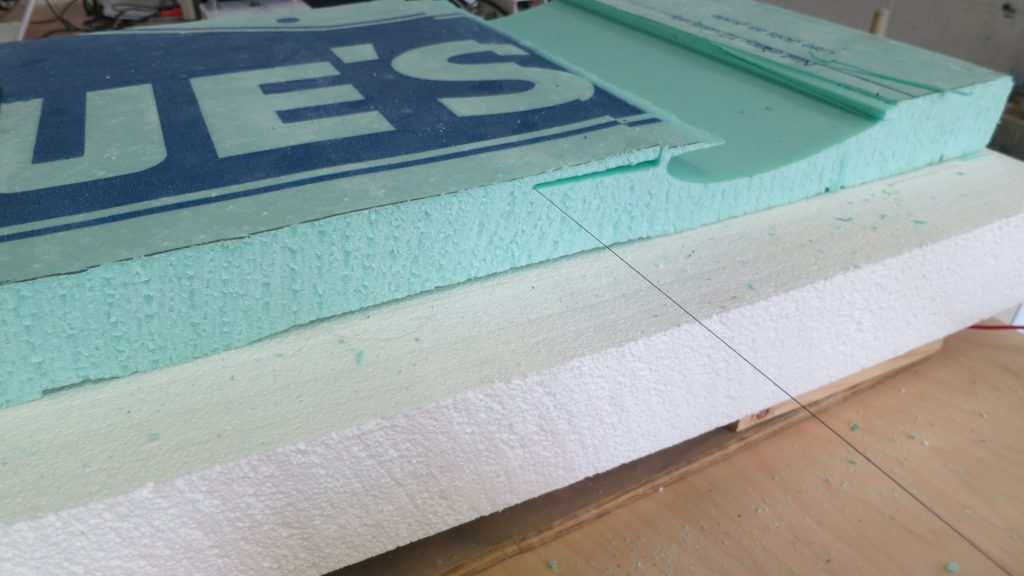
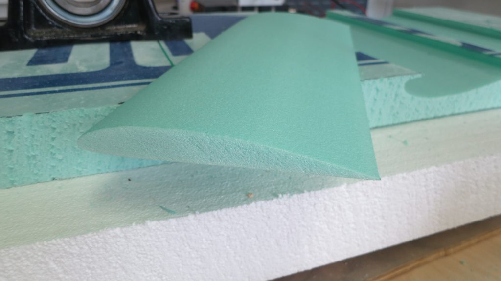
The CNC foam cutter is a robotic cutting machine that uses a taut electrically heated wire to melt through expanded styrene foam such as common home insulation. The process can create decent surface finishes while maintaining good dimensional accuracy. Let’s go through the process of cutting a foam airfoil from SolidWorks to finished product.
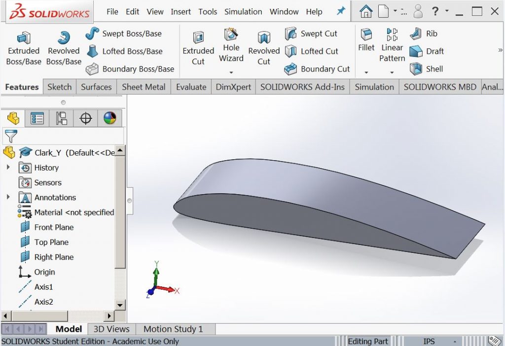
First draw the part in Solidworks.
and then create a drawing
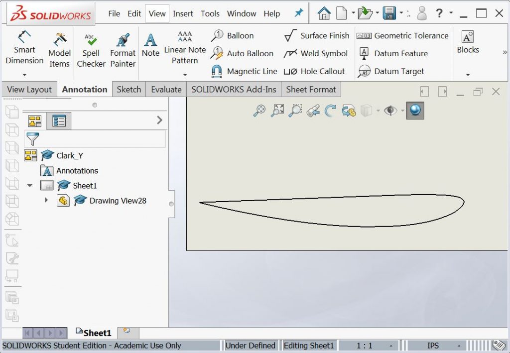
The drawing should be 1:1 scale, have all the hidden lines turned off, the format deleted, and any dimensions, centerlines, centermarks, and any other annotations removed. The only remaining items should be the lines you are going to cut. This drawing should be saved as a DXF file on a flash drive.
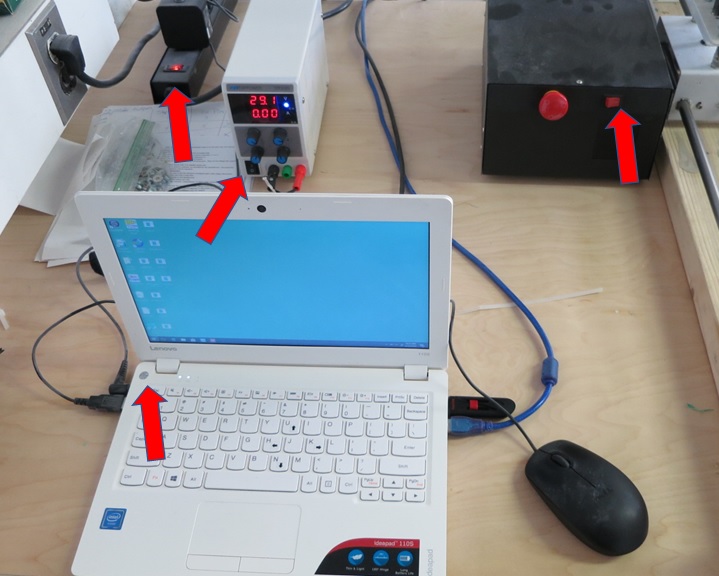
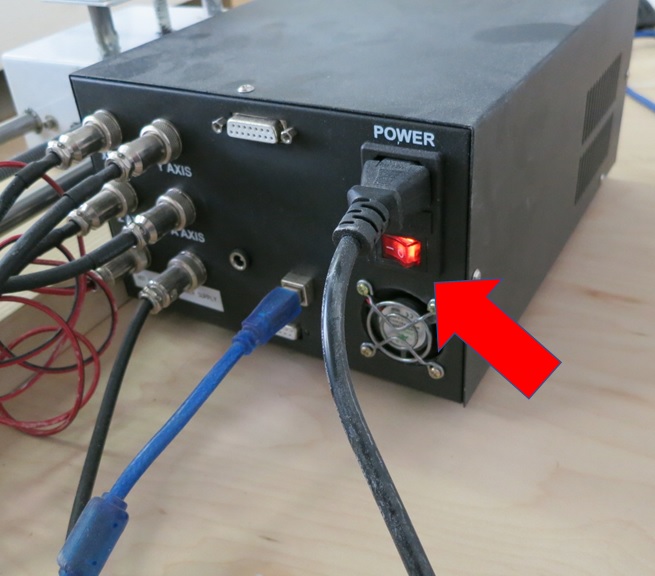
Now it’s time to turn on the hot wire machine. The power switches are indicated by the red arrows.
Once the computer is fully booted up start the DevFoam software.

After the program launches hit FILE>New and import the DXF you created in SolidWorks. You should have a screen that looks like this:
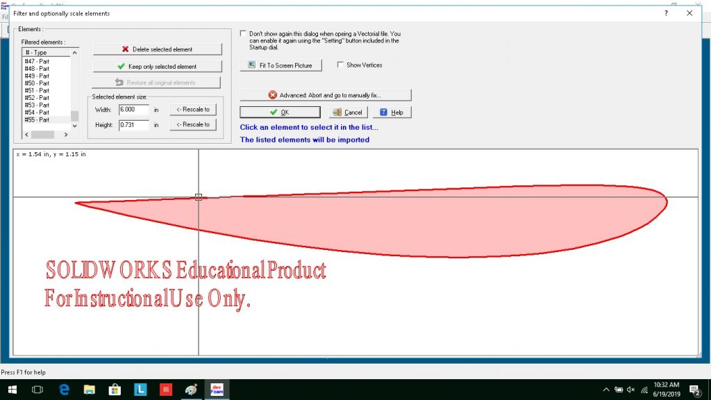
Since we will not need the SolidWorks legal statement, click on the object you want to keep and then click “Keep only selected element”. You should be left with just your desired geometry. Clicking OK will bring you to this next screen where we will create the toolpath and set the part’s depth into the stock.
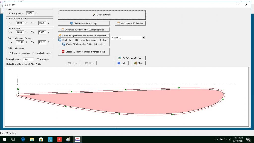
Clicking “Create cut path” creates the pathway for the hot wire. I like starting my cuts with the wire on the surface of a piece of foam and cutting downward. Unfortunately my model was draw in the +Y quadrant. This would result in an “air cut” rather than cutting the foam. To fix the problem a -.875″ offset was applied and the cut path was regenerated.
Depending on the thickness of your foam you may want to change the feed rate of you wire. This control is under “Customize G Code or other cutting properties” Cutting through twenty four inches of foam 10 in/min gave a nice surface finish.
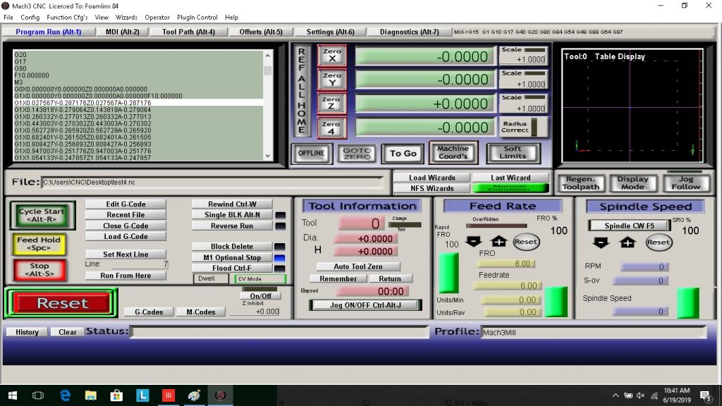
Cutting is not actually done in the devFoam program. You will need to save the cutter pathway as G-code, the universal language of CNC machines, before we actually do the cutting in Mach3Mill.
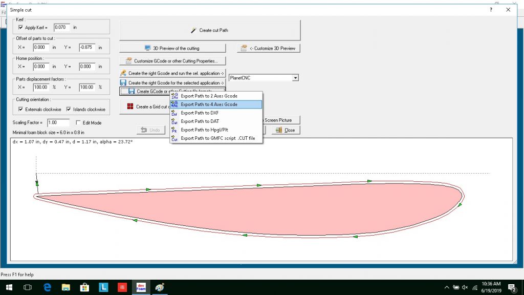
Four axis G code is required to independently control the four stepper motors that drive the machine. Inside the machine the controller associates the horizontal left axis to X in the G code, vertical left to Y, vertical right to A, and horizontal right to the Z axis.
The code written by Dev Foam should look like this minus the comments. Those were added for readability. The machine would accept and ignore them:
G20 (Program in inches)
G17 (Select the XY plane)
G90 (Absolute distance mode)
F10.000000 (Feed rate of 10 in/min)
M3 (Activate wire heating)
G0X0.000000Y0.000000Z0.000000A0.000000 (G0=Rapid traverse to a position)
G1X0.000000Y0.000000Z0.000000A0.000000F10.000000 (G1=Perform cutting move at a feed rate of 10 in/min)
G1X0.027567Y-0.287176Z0.027567A-0.287176
G1X0.143818Y-0.279064Z0.143818A-0.279064
etc., etc.,
After all the cutting is done ….
G0X0.000000Y0.000000Z0.000000A0.000000 (Rapid traverse back to the start point)
M5 (Turn off the power to the wire.)
At this point we can close devFoam and open Mach3.
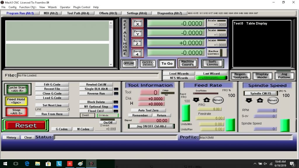
You will need to click the reset button to start using the program. Next click the load G-Code button and select your program.
So far so good!
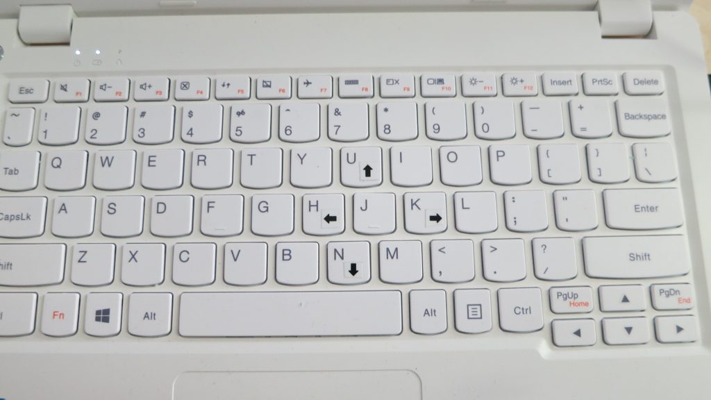
Next we will need to position the cutting wire by jogging the machine. The machine can be manually moved using these arrows on the keyboard:
Position the wire on top of the foam at the desired start point. Add a weight to the foam so that it will not shift while cutting. Lastly click the zero X, zero Y, zero Z, and Zero4 buttons. This establishes the origin for your program at the current wire location.
Just about there!!! Now hit “Cycle Start”. The cutter should begin moving.
Lastly and most importantly, when you are done turn everything off and clean up the work area.