Heart Rate Monitor and Pulse Oximeter - H.A.L.O. Mk. 1
Monitoring a pilot’s heart rate and blood oxygen saturation is critical to determine cases of tachycardia (abnormally high heart rate), bradycardia (abnormally low heart rate), arrhythmia (irregular heart rate), and hypoxia (oxygen deficiency). These two pieces of information can warn the user of a potential medical emergency, such as a heart attack or stroke, that would inhibit the pilot’s ability to fly safely.
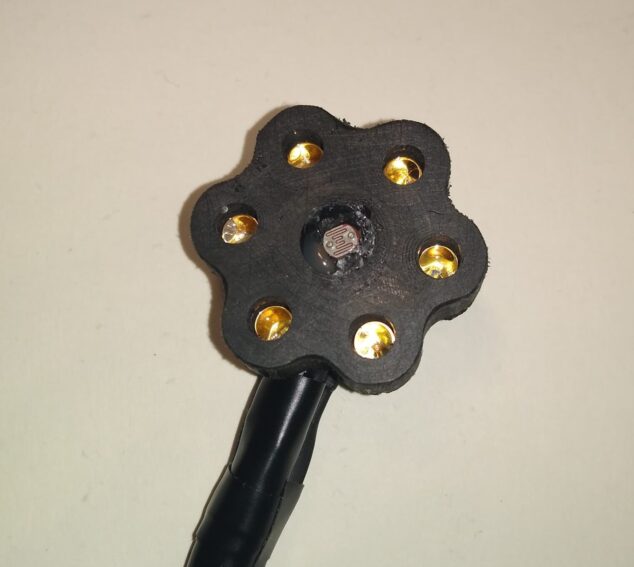
The heart rate monitor and pulse oximeter (HRMPO) was assembled by inserting six LED lights (two 430nm blue/green LEDs, two 625nm red LEDs, and two 970nm infrared LEDs) into a 3D printed PLA plastic casing as shown to the right. Each LED pair is positioned directly across a photoresistor, which is positioned in the middle so that incoming light is equal from both sides. The green/blue LED is used for the heart rate monitor since red blood cells absorb green light efficiently. With each heart beat, a pressure wave is sent through the body’s blood vessel system and expands the blood-carrying arteries. As a result of this expansion, a higher volume of blood passes in front of the sensor and leads to increased light absorbance. The sensor then detects a decrease in light intensity as less light is reflected back towards the photoresistor.
Pulse oximetry is also measured by this sensor and requires information from two different wavelengths. Oxygenated blood absorbs 970nm infrared light efficiently while deoxygenated blood absorbs 625nm red light. If the two light sources are set to the same intensity, the ratio of absorbances is indicative of the ratio of oxygenated blood to deoxygenated blood, which is then converted to a saturation percentage.
The sensor itself is small, with a 8mm thickness and a 36.8mm. diameter. The sensor is inserted into a headband where it will take measurements from the pilot’s forehead.


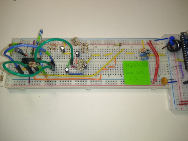
Since fluctuations in light intensity due to blood absorbance are small, the signal read from the photoresistor has to be amplified and refined. The overall expected range for a heart rate is 30bpm to 220bpm, which is directly translated to a frequency range of 0.5 Hz to 3.67 Hz. The filter circuit shown to the left consists of multiple high-pass and low-pass filters which eliminate frequency noise from external distractions such as ambient light, cellular signals, and internet signals. The circuit altogether was designed as a Butterworth filter to allow the more accurate truncation of the filtered signals.
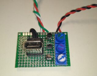
Since the LEDs require a stable power source, the board was isolated and miniaturized to prohibit interference between the frequency output of the board and the output of the sensor. The sensor itself plugs into the power supply with a USB connection for ease of replacement, and allows the sensor to be isolated from the power supply when the sensor is not in use because the components are static sensitive.

The heart rate monitor was tested by placing the device over the temporal artery. This placement was chosen due to the large diameter of the vessel which allows for a larger volume of blood and higher absorbance overall. Data was collected for 60 seconds, with heart rate being calculated every 10 seconds.
Results of the test can be seen to the left. In this case, the signal is inverted because an increase in vessel diameter results in a higher absorbance of light, thus light intensity is decreased.
These calculated values were compared to a gold standard ContecTM 50DL optical heart rate monitor and pulse oximeter. An error of 4.95% was calculated with an overall sensor accuracy of 95.05%.

Unfortunately due to technical errors, data for the pulse oximeter could not obtained at this time. One of the 970nm infrared LED lights was defective, and ordering parts at this time is not feasible.
